CODE | Control Stepper Motor ULN2004A - Arduino Project 029
Stepper motors, due to their unique design, can be controlled to a high degree of accuracy without any feedback mechanisms. The shaft of a stepper, mounted with a series of magnets, is controlled by a series of electromagnetic coils that are charged positively and negatively in a specific sequence, precisely moving it forward or backward in small "steps".
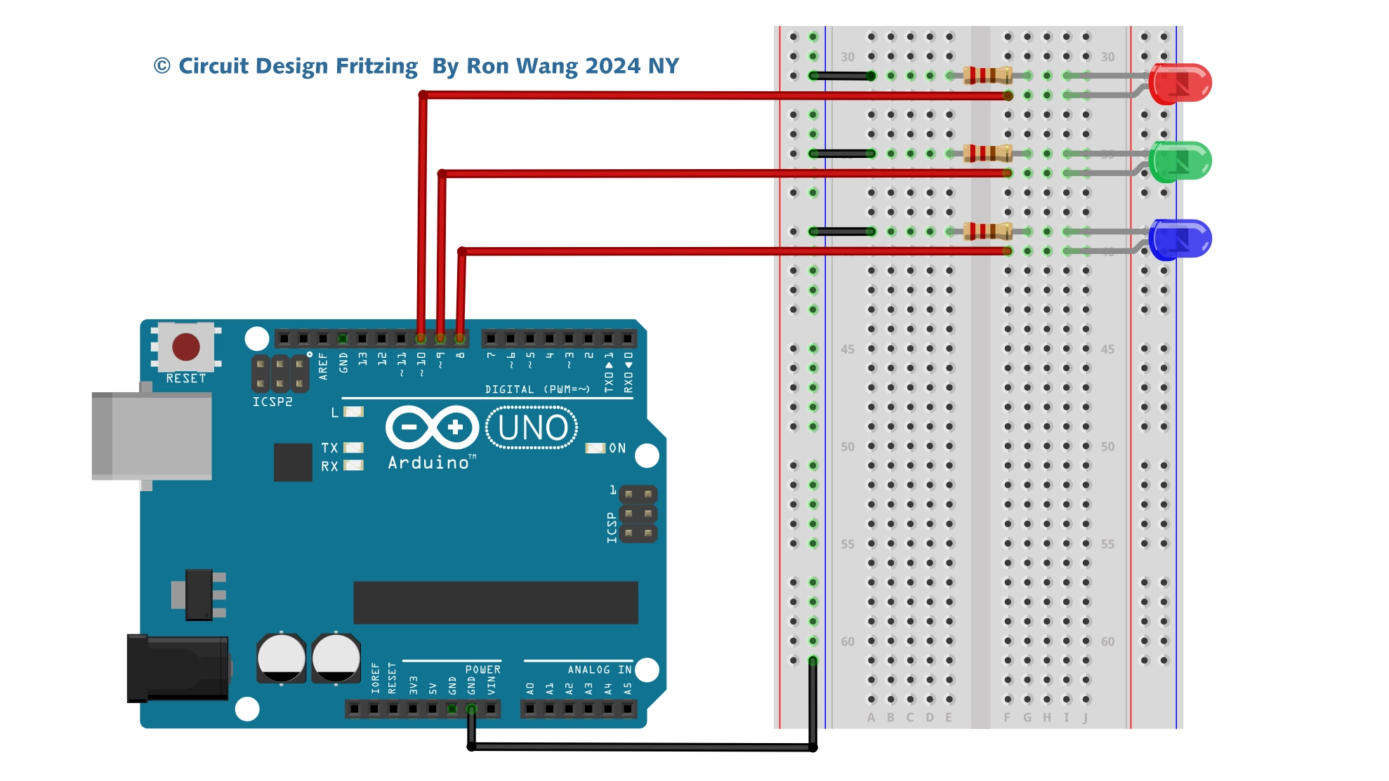
There are two types of steppers, Unipolars and Bipolars, and it is very important to know which type you are working with. For each of the motors, there is a different circuit. The example code will control both kinds of motors. See the unipolar and bipolar motor schematics for information on how to wire up your motor.
The stepper is controlled by with digital pins 8, 9, 10, and 11 for either unipolar or bipolar motors. The Arduino board will connect to a U2004 Darlington Array if you're using a unipolar stepper or a SN754410NE H-Bridge if you have a bipolar motor.
ULN2003A VS ULN2004A
The ULN2001, ULN2002, ULN2003 and ULN 2004 are high-voltage, high-current Darlington arrays each containing seven open collector Darlington pairs with common emitters. Each channel is rated at 500 mA and can withstand peak currents of 600 mA. Suppression diodes are included for inductive load driving and the inputs are pinned opposite the outputs to simplify board layout.
The versions interface to all common logic families: ULN2001 (general purpose, DTL, TTL,PMOS, CMOS); ULN2002 (14 - 25 V PMOS); ULN2003 (5 V TTL, CMOS); ULN2004 (6 - 15 V CMOS, PMOS).
These versatile devices are useful for driving a wide range of loads including solenoids, relay DC motors, LED display filament lamps, thermal printheads and high-power buffers.
Detail information :ULN200xx.fm
Arduino Project 029 - Control Stepper Motor ULN2004
/* Coding Ron Wang
   Nov.19th 2024
   Autaba support for coding hardware
   Project 29 - Motor Shield ULN2003 IC potentiometer
 */
#include <Stepper.h>
#define STEPS 100  // set the number of steps on your motor
Stepper stepper(STEPS, 8, 9, 10, 11);  // Set the stepper motor pin
int previous = 0;  // the previous reading from the analog input A0
void setup() {

  stepper.setSpeed(40); // set the speed of the motor to 40 RPMs
}
void loop() {

  int val = analogRead(0); // get the sensor value
 // move a number of steps equal to the change in the sensor reading
  stepper.step(val - previous);
  previous = val; // remember the previous value of the sensor
}
ULN2004 IC Connect the Unipolar motor circuit

ULN2004 IC Connect the Unipolar motor Schematic

L293D / SN754410NE H-Bridge IC Connect Bipolar Stepper Motor Circuit

L293D / SN754410NE H-Bridge IC Connect Bipolar Stepper Motor Schematic

ULN2003A IC Shield Circuit

ULN2003A IC Shiled Schematic
Stepper Control Examples
StepperOneRevolution
The motor should revolve one revolution in one direction, then one revolution in the other direction.
#include <Stepper.h>

const int stepsPerRevolution = 200;

// set this to fit the number of steps per revolution for your motor
// initialize the stepper library on pins 8 through 11:

Stepper myStepper(stepsPerRevolution, 8, 9, 10, 11);
void setup() {

  myStepper.setSpeed(60); // set the speed at 60 rpm:

  Serial.begin(9600); // initialize the serial port:
}
void loop() {
  // step one revolution  in one direction:

  Serial.println("clockwise");
  myStepper.step(stepsPerRevolution);
  delay(500);

  // step one revolution in the other direction:

  Serial.println("counterclockwise");
  myStepper.step(-stepsPerRevolution);
  delay(500);
}
Stepper One Step At Time
The motor will step one step at a time, very slowly. You can use this to test that you've got the four wires of your stepper wired to the correctpins. If wired correctly, all steps should be in the same direction.
#include <Stepper.h>

const int stepsPerRevolution = 200;
// set this to fit the number of steps per revolution for your motor
// initialize the stepper library on pins 8 through 11:

Stepper myStepper(stepsPerRevolution, 8, 9, 10, 11);
int stepCount = 0;    // number of steps the motor has taken

void setup() {
  // initialize the serial port:
  Serial.begin(9600);
}

void loop() {
  // step one step:
  myStepper.step(1);
  Serial.print("steps:");
  Serial.println(stepCount);
  stepCount++;
  delay(500);
}
Stepper Speed Control
The motor will rotate in a clockwise direction. The higher the potentiometer value, the faster the motor speed. Because setSpeed() sets the delay between steps, you may notice the motor is less responsive to changes in the sensor value at low speeds.
#include <Stepper.h>
const int stepsPerRevolution = 200;
// set this to fit the number of steps per revolution for your motor
// initialize the stepper library on pins 8 through 11:
Stepper myStepper(stepsPerRevolution, 8, 9, 10, 11);
int stepCount = 0;  // number of steps the motor has taken
void setup() {
  // nothing to do inside the setup
}
void loop() {
  // read the sensor value:
  int sensorReading = analogRead(A0);
  // map it to a range from 0 to 100:
  int motorSpeed = map(sensorReading, 0, 1023, 0, 100);
  // set the motor speed:
  if (motorSpeed > 0) {
    myStepper.setSpeed(motorSpeed);
    // step 1/100 of a revolution:
    myStepper.step(stepsPerRevolution / 100);
  }
}