SAE J2601 Appendix F Dispenser Fuel Delivery Temp.&Control Spec.17
Appendix F Dispenser Fuel Delivery Temperature and Control Specification
F.1 DISPENSER FUEL DELIVERY TEMPERATURE AND COMMUNICATIONS SPECIFICATION
Fueling dispenser flow restriction shall be upstream of vehicle interface. Fueling dispenser shall be capable of setting the temperature of the fuel delivery temperature hydrogen gas at the break-away consistent with the fueling protocol.
Installation of fuel delivery temperature equipment shall be downstream of the smallest flow restriction in the complete fueling path. Otherwise, the Joule-Thomson effect will lead to a significant temperature increase of the hydrogen gas delivered to the vehicle, thereby making the fuel delivery temperature less effective.
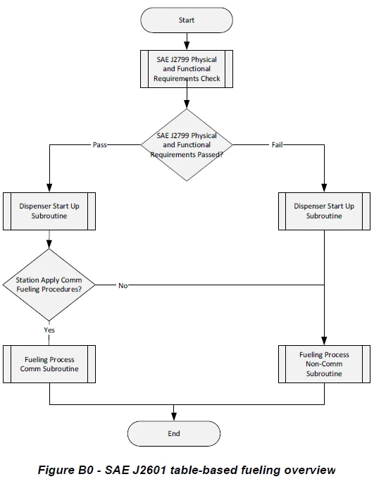
If a station has communications fueling capability, the fueling dispenser shall be capable of fueling vehicles with and without communications between the vehicle and dispenser.
F.2 PRESSURE CONTROL
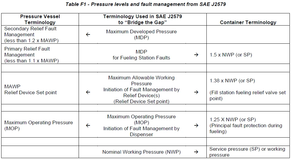
The fueling station shall execute three levels of pressure control; see Table F1 for pressure levels and fault management.
• 1st Level (normal control process): Terminate fueling when target pressure (from SAE J2601 tables) is reached.
• 2nd Level (principal fault management: redundant electronic protection level): Terminate fueling when 125% NWP (87.5 MPa for a 70 MPa dispenser; 43.8 MPa for a 35 MPa dispenser) is reached.
• 3rd Level (secondary fault management: fully mechanical protection level): When fueling station PRV set point is reached. The PRV set point should be no greater than 1.25*NWP +10% = 1.375*NWP (96.25 MPa for a 70 MPa dispenser and 48.13 MPa for a 35 MPa dispenser).