
CODE | MX1508 H-Driver Motor - Arduino Project 030B
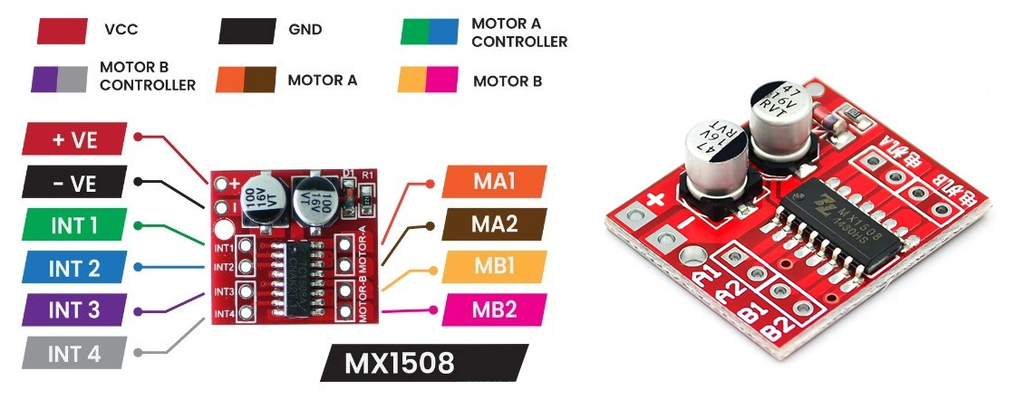
MX1508 H-BridgeDual Motor Driver
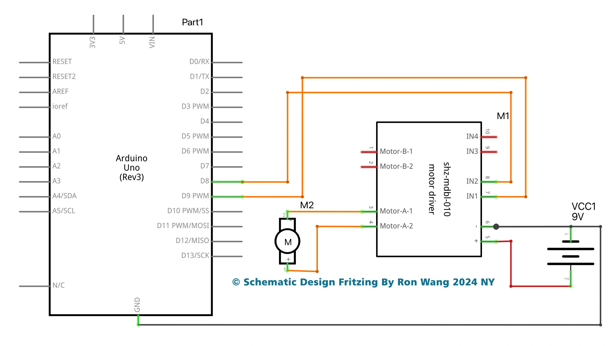
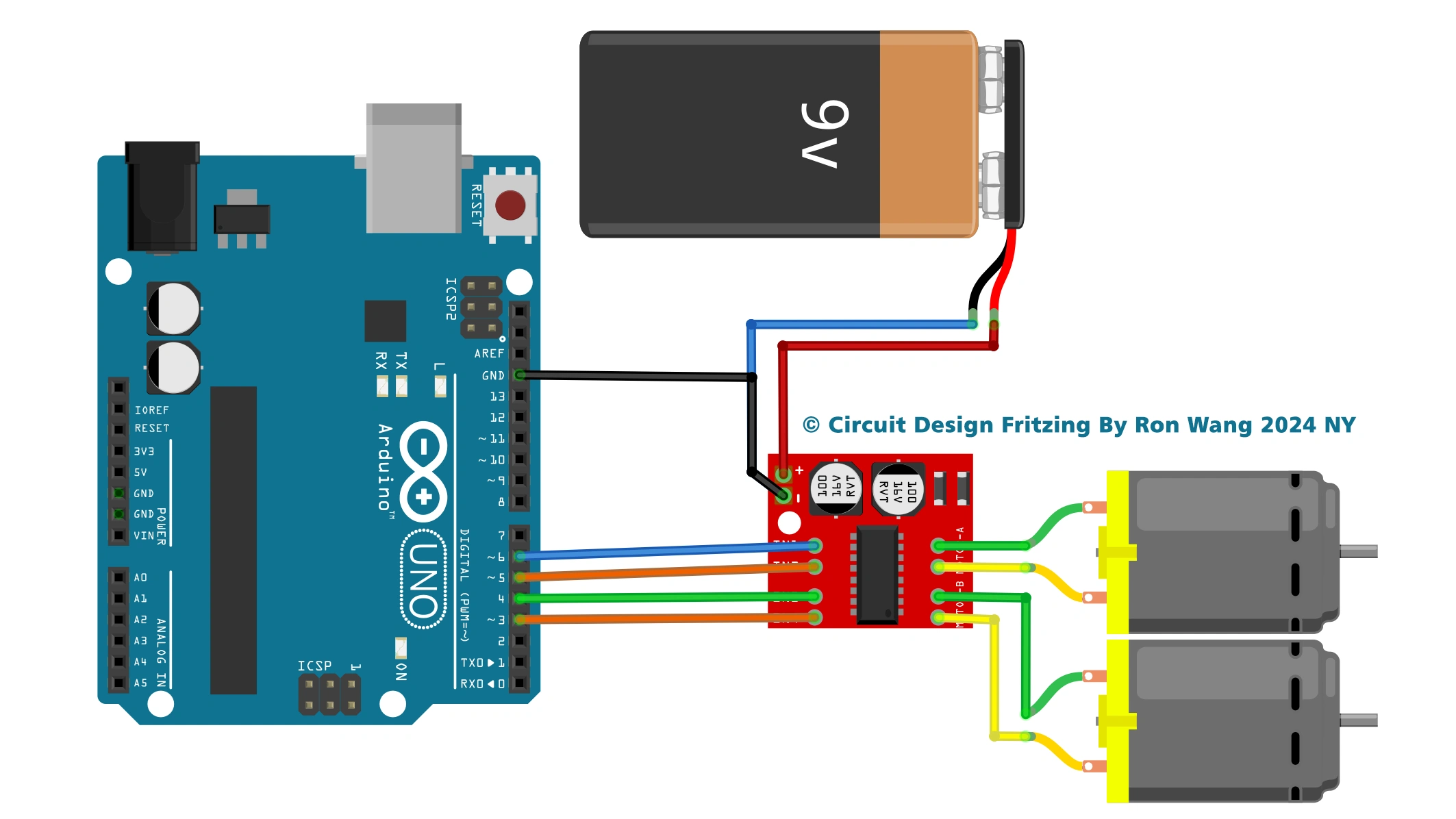
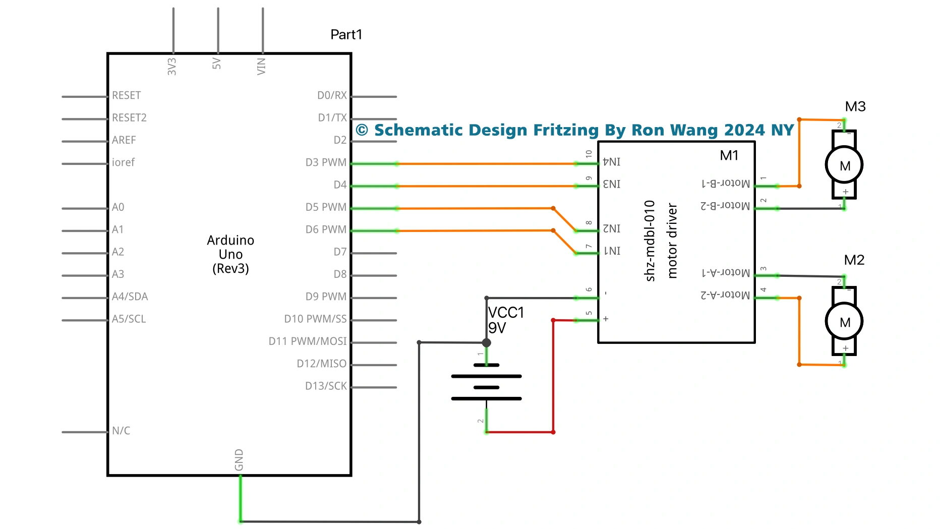
The driver can drive up to two motors. The H-Bridge dual motor driver module is connected to the arduino where it receives signals. The signal pins on the driver are four, two for each motor. One signal pin makes the motor move in a particular direction of rotation but the other one makes it move the opposite way. This same principle works for the other motor. The driver receives an input voltage from 5v to 12v . There is a voltage regulator that sets the voltage down. This power source can be used to power the arduino board.
/*
  MX1508 DC MOTOR DRIVER MODULE
  One Motor Project
*/
void setup() {
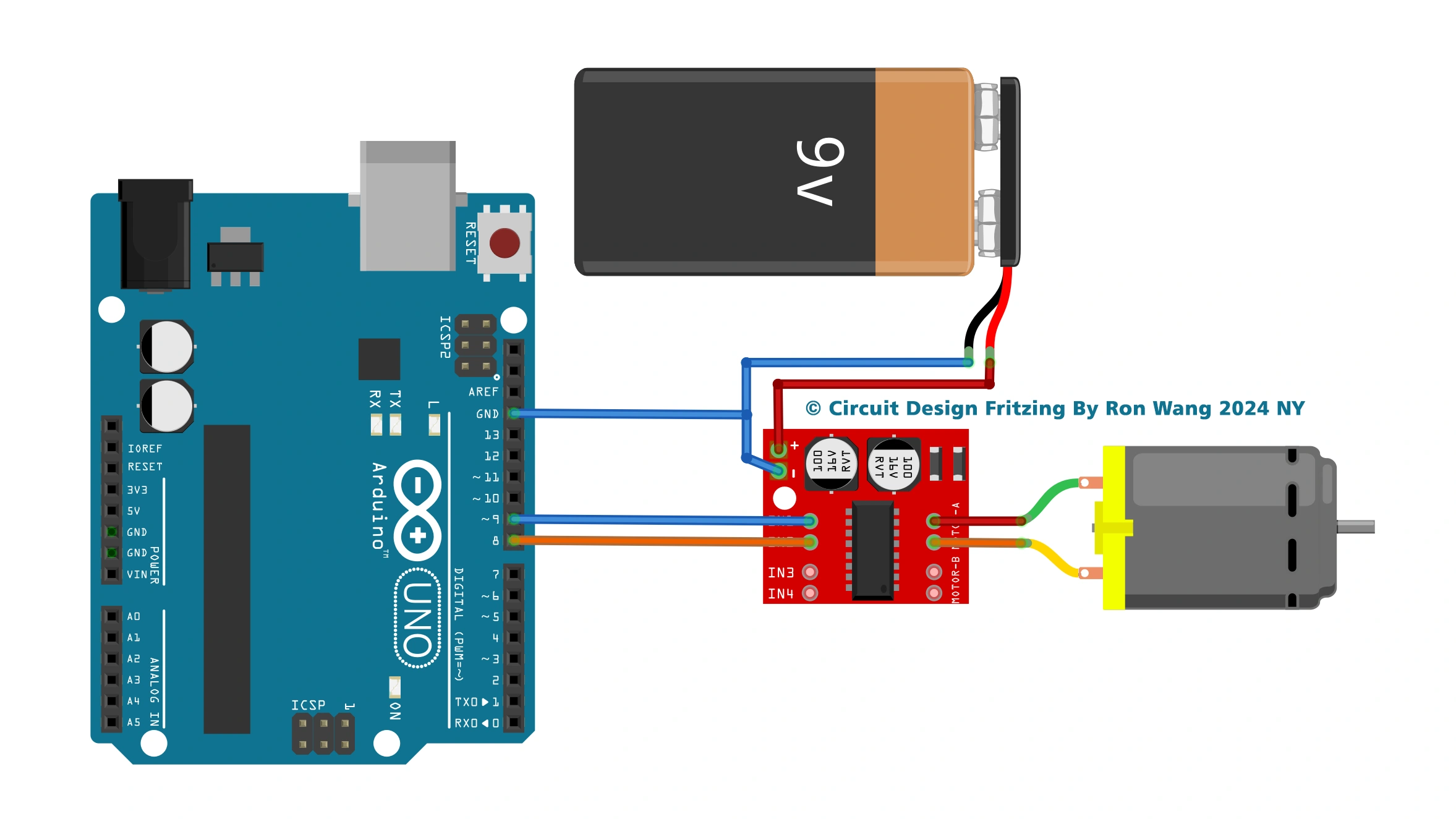
  pinMode(8, OUTPUT); //IN2
  pinMode(9, OUTPUT); //IN1
}
void loop() {
// Full speed forward
  digitalWrite(8, HIGH);
  digitalWrite(9, LOW);
  delay(3000);
// Full speed backward
  digitalWrite(8, LOW);
  digitalWrite(9, HIGH);
  delay(3000);
// 0 to 100% speed in forward mode
  for (int i=0;i<256;i++)
  {   digitalWrite(8, HIGH);
      analogWrite(9, i);
      delay(30);
      }
  delay(60);
  // 0 to 100% speed in backward mode
        for (int i=255;i<0;i--)
  {   digitalWrite(8, LOW);
      analogWrite(9, i);
      delay(30);
      }
        delay(60);
}
/*
  MX1508 DC MOTOR DRIVER MODULE
  Dual motor project
*/

int motor1clockwise=3; // motor one clockwise signal connected to pin 3
int motor1anticlockwise=4; //motor one anticlockwise signal connected to pin 4
int motor2clockwise=5; //motor two clockwise signal connected to pin 5
int motor2anticlockwise=6; // motor two anticlockwise signal connected to pin 6
void setup(){
Serial.begin(9600);
//  declare all motor pins as OUTPUTS
pinMode(motor1clockwise,OUTPUT);
pinMode(motor1anticlockwise,OUTPUT);
pinMode(motor2clockwise,OUTPUT);
pinMode(motor2anticlockwise,OUTPUT);
}
void loop(){
digitalWrite(motor1clockwise,HIGH); //move motor one clockwise
delay(1000);
digitalWrite(motor1clockwise,LOW); //stop motor one clockwise
digitalWrite(motor1anticlockwise,HIGH); //move motor one anticlockwise
delay(1000);
digitalWrite(motor1anticlockwise,LOW); //stop motor one anticlockwise
digitalWrite(motor2clockwise,HIGH); //move motor two clockwise
delay(1000);
digitalWrite(motor2clockwise,LOW); // stop motor two clockwise
digitalWrite(motor2anticlockwise,HIGH); //move motor two anticlockwise
delay(1000);
digitalWrite(motor2anticlockwise,LOW); // stop motor two anticlockwise
}