CODE | Simple Ultrasonic Range HC-SR04 - Arduino Project 038
Ultrasonic range finders measure distance by emitting a pulse of ultrasonic sound that travels through the air until it hits an object. When that pulse of sound hits an object, it’s reflected off the object and travels back to the ultrasonic range finder. The ultrasonic range finder measures how long it takes the sound pulse to travel in its round trip journey from the sensor and back. It then sends a signal to the Arduino with information about how long it took for the sonic pulse to travel.
Knowing the time it takes the ultrasonic pulse to travel back and forth to the object, and also knowing the speed of sound, the Arduino can calculate the distance to the object. The formula relating the speed of sound, distance, and time traveled is:
Distance formula equals speed multiplied by time.Rearranging this formula.
The time variable is the time it takes for the ultrasonic pulse to leave the sensor, bounce off the object, and return to the sensor. We actually divide this time in half since we only need to measure the distance to the object, not the distance to the object and back to the sensor. The speed variable is the speed at which sound travels through air.
General Speed of sound in air = 344 m/s
The speed of sound in air changes with temperature and humidity. Therefore, in order to accurately calculate distance, we’ll need to consider the ambient temperature and humidity. The formula for the speed of sound in air with temperature and humidity accounted for is:
C= 331.4+(0.606XT)+(0.0124XH)
C:Speed of sound in meters per second(m/s)
331.4 : Speed fo sound (in m/s)at 0 centigrade degree and zero percent humidity.
T: Temperature in 0 centigrade degree.
H: % Humidity (relative humidity).
In the equation speed of sound , it’s clear that temperature has the largest effect on the speed of sound. Humidity does have some influence, but it’s much less than the effect of temperature.
The Ultrasonic Range Finder Measures Distance
On the front of the ultrasonic range finder are two metal cylinders. These are transducers. Transducers convert mechanical forces into electrical signals. In the ultrasonic range finder, there is a transmitting transducer and receiving transducer. The transmitting transducer converts an electrical signal into the ultrasonic pulse, and the receiving transducer converts the reflected ultrasonic pulse back into an electrical signal. If you look at the back of the range finder, you will see an IC behind the transmitting transducer labelled MAX3232. This is the IC that controls the transmitting transducer. Behind the receiving transducer is an IC labelled LM324. This is a quad Op-Amp that amplifies the signal generated by the receiving transducer into a signal that’s strong enough to transmit to the Arduino
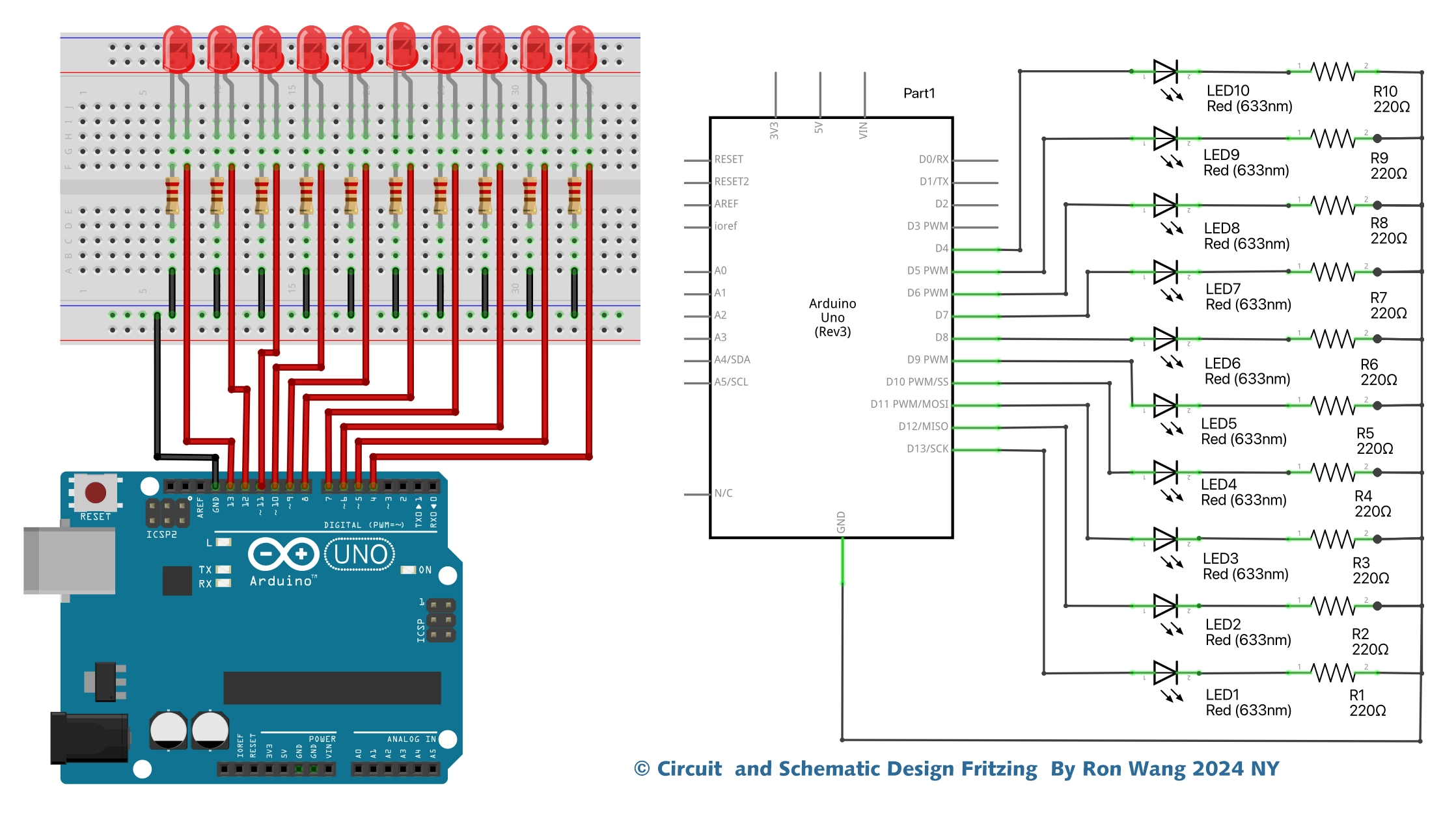
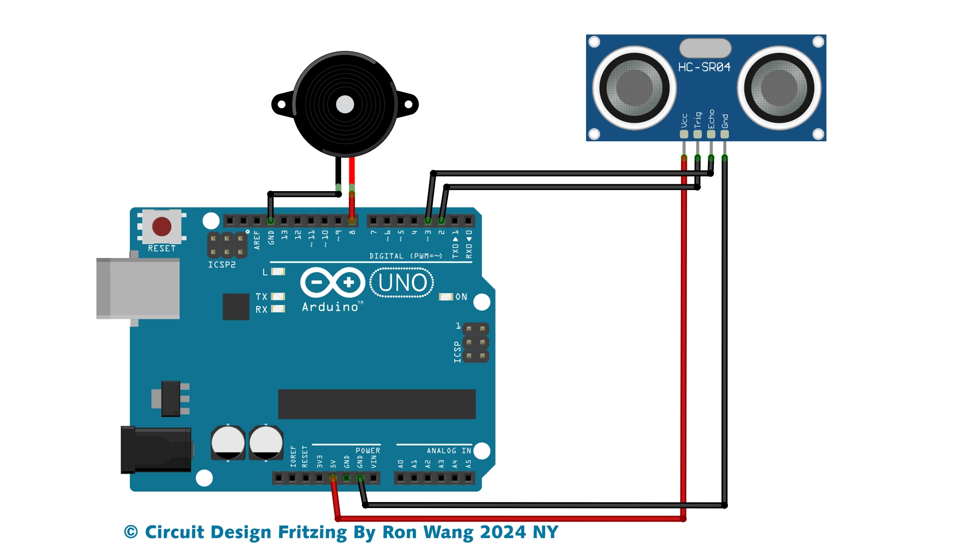
The HC-SR04 ultrasonic range finder has four pins:
Vcc – supplies the power to generate the ultrasonic pulses
GND – connected to ground
Trig – where the Arduino sends the signal to start the ultrasonic pulse
Echo – where the ultrasonic range finder sends the information about the duration of the trip taken by the ultrasonic pulse to the Arduino
To initiate a distance measurement, we need to send a 5V high signal to the Trig pin for at least 10 µs. When the module receives this signal, it will emit 8 pulses of ultrasonic sound at a frequency of 40 KHz from the transmitting transducer. Then it waits and listens at the receiving transducer for the reflected signal. If an object is within range, the 8 pulses will be reflected back to the sensor. When the pulse hits the receiving transducer, the Echo pin outputs a high voltage signal.
The length of this high voltage signal is equal to the total time the 8 pulses take to travel from the transmitting transducer and back to the receiving transducer. However, we only want to measure the distance to the object, and not the distance of the path the sound pulse took. Therefore, we divide that time in half to get the time variable in the d = s x t equation above. Since we already know the the speed of sound (s), we can solve the equation for distance.
Project 38 Simple Ultrasonic Range HC-SR04


/* Coding by Ron Wang
 * Dec.3rd 2024
 * Autaba support for Coding Hardware
 * Project 38 Simple Ultrasonic Range
 * HC-SR04 example sketch
*/

const int trigPin = 9;
const int echoPin = 8;
float duration, distance;

void setup() {
  pinMode(trigPin, OUTPUT);
  pinMode(echoPin, INPUT);
  Serial.begin(9600);
}

void loop() {
  digitalWrite(trigPin, LOW);
  delayMicroseconds(2);
  digitalWrite(trigPin, HIGH);
  delayMicroseconds(10);
  digitalWrite(trigPin, LOW);
  duration = pulseIn(echoPin, HIGH);
  distance = (duration*.0343)/2;  // Distance unit cm
  Serial.print("Distance: ");
  Serial.println(distance);
  delay(100);
}