SAE J2601 Appendix J MC Formula-Based Equations & Coefficients 20
APPENDIX J - SAE J2601 MC FORMULA-BASED EQUATIONS AND COEFFICIENTS
This appendix details the parameters, equations and formulas for implementing the MC Formula-based protocol. This appendix should be utilized in conjunction with the flow charts in Appendix I. Each subroutine in the Appendix I flow charts is directly referenced to a section of this appendix. The flow charts should be utilized as a means for understanding the order of the calculations required, whereas the subroutines detailed in this appendix should be utilized as a means for understanding the specific parameters, equations, and formulas required.
All equations in the dispenser startup subroutine and the fueling process subroutine of Appendix J shall be implemented as stated, and shall follow the order of calculation as defined in the flow charts in Appendix I.
Although an explanation for each parameter and equation, as well as guidance for their use, is provided, Section 3 should be utilized as a reference for definitions, and Section 4 as a reference for abbreviations and symbols utilized in the subroutines. Additionally, Appendix H should be referenced for a more thorough explanation of the structure and derivation of the MC Formula-based protocol.
J.1 DISPENSER STARTUP SUBROUTINE
The dispenser startup subroutine is used to determine essential initial conditions which are utilized in the fueling process subroutine. The flow chart for the dispenser startup subroutine is shown in Figure I1.
J.1.1 Check for Fueling Command Abort
The dispenser first checks if there is an abort from the IR communication data field named FC. If there is an abort, the dispenser shall terminate the startup process. If there is not an abort command, the dispenser next checks that the ambient temperature is within the defined limits.
J.1.2 Initial Pressure Pulse, Leak Check, and Determine Initial CHSS Pressure
An initial pressure pulse equilibrates the station pressure and CHSS pressure. If utilized, a leak check routine is implemented right after the initial pressure pulse. If the leak check fails, the dispenser shall terminate the startup process. If the leak check passes, or if the leak check routine is not utilized, the dispenser then measures the initial CHSS pressure, and stores this value as Pinitial.
J.1.3 Cold Dispenser Fueling
If the dispenser has implemented cold dispenser fueling, as described in 9.10, the dispenser checks the station component temperature against the cold dispenser criteria to determine if the cold dispenser tfinal coefficients can be utilized. If the cold dispenser criteria are met according to 9.10, the dispenser sets the flag variable CD to TRUE. Otherwise, if the cold dispenser criteria are not met, or if cold dispenser fueling is not utilized, the dispenser sets the flag variable CD to FALSE.
J.1.4 CHSS Volume and CHSS Capacity Category Determination
The dispenser next determines the CHSS volume and from this, the CHSS Capacity Category CHSSCapacity_Category. The MC Formula-based CHSS capacity category is defined in 9.2, Table 8.
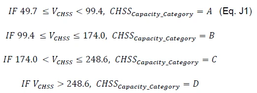
There are two pathways for determining the CHSS volume - one for use with communication fueling, and the other for use with non-communication fueling.