CODE | Line Following Robot - Arduino Project 030
Project 30 Line Following Robot
A line following robot is an autonomous vehicle that detects and follows a path, usually a black line on a white surface, using IR sensors. The Arduino processes sensor data and controls motors to keep the robot on track.
Steps to Build
1. Gather Components
Arduino UNO
L293D or L298N motor driver
2 IR sensor modules
2 DC geared motors + wheels
Chassis + caster wheel
7.4V–9V battery pack
Jumper wires
2. Assemble the Hardware
Mount motors and wheels on the chassis.
Fix IR sensors at the front, ~5mm above the ground, spaced so the line passes between them.
Connect motor driver inputs to Arduino digital pins, outputs to motors, and enable pins to PWM pins for speed control.
Connect IR sensor outputs to Arduino digital pins (e.g., 2 and 4).
3. Upload Arduino Code The logic:
Both sensors detect white → Move forward
Left detects black → Turn left
Right detects black → Turn right
Both detect black → Stop
Use L298P Driver Line Following Robot

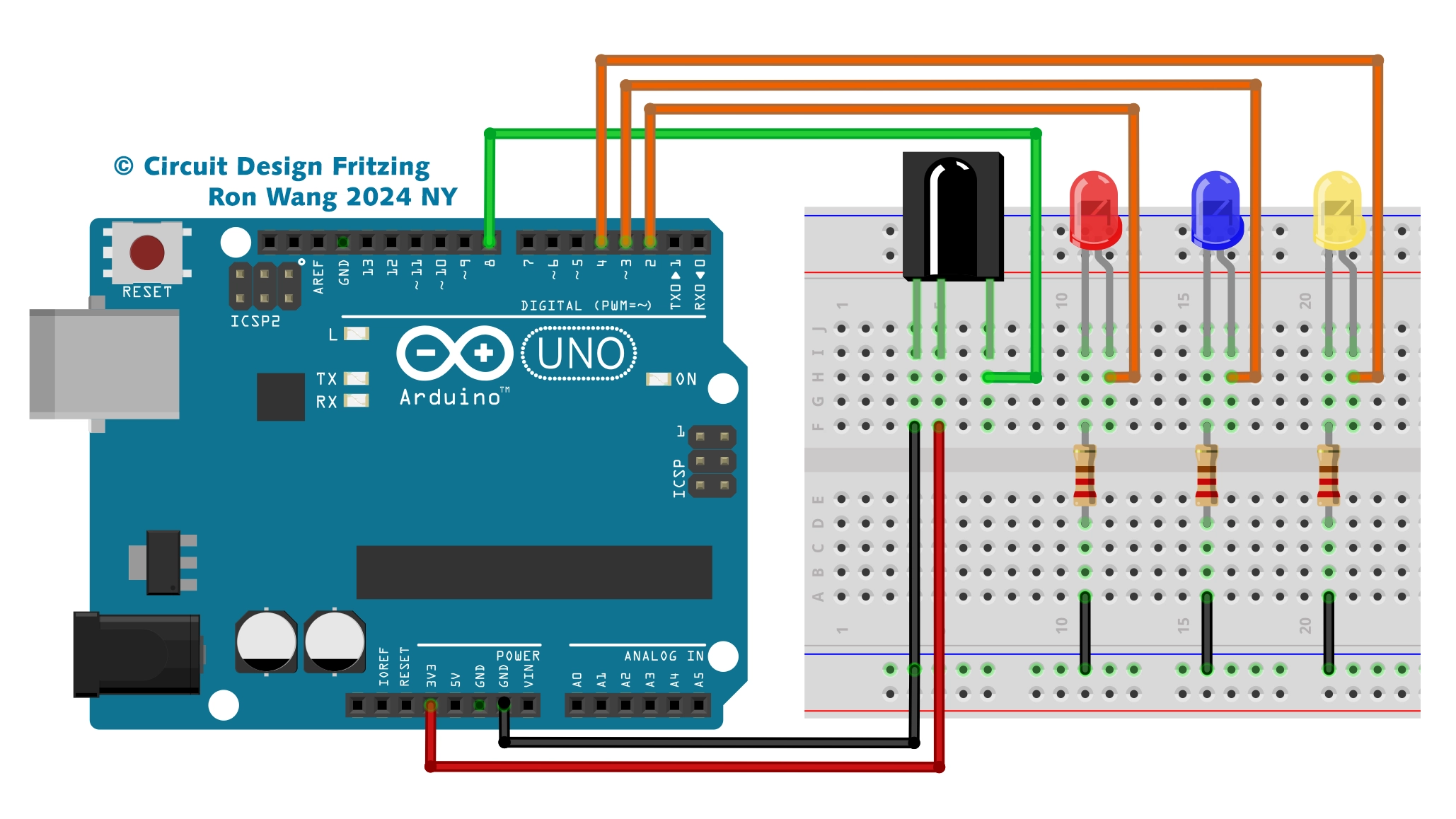
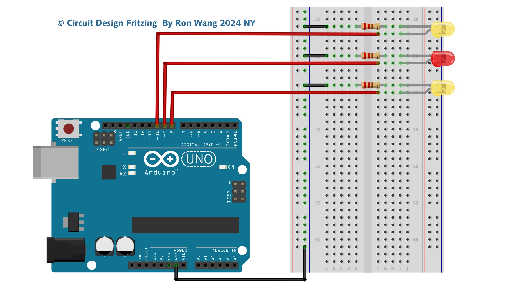
Line or Trace Following Robot Circuit

Line or Trace Following Robot Schematic
/* Coding Ron Wang
   Nov.21th 2024
   Autaba support for coding Hardware
   Project 30  Tracking Line Robot
 */

int mr1=8;  //motor right 1
int mr2=9;  //motor right 2
int ml1=10; //motor left 1
int ml2=11; //motor left 2
int sr=6;   //sensor right
int sl=7;   //sensor left
int svr=0;
int svl=0;
int led=13;
int enr=3;
int enl=5;
int vspeed=100;
int tspeed=255;
int tdelay=20;

void  setup()
{
 pinMode(mr1,OUTPUT);
 pinMode(mr2,OUTPUT);
 pinMode(ml1,OUTPUT);
  pinMode(ml2,OUTPUT);
 pinMode(led,OUTPUT);
 pinMode(sr,INPUT);
 pinMode(sl,INPUT);

 delay(5000);
}

void loop()
{
 svr=digitalRead(sr);
 svl=digitalRead(sl);

  if(svl==LOW && svr==LOW)
  {
  forward();   // Forward
  }
  if(svl==HIGH  && svr==LOW)
  {
  left();     //Turn left
  }

  if(svl==LOW && svr==HIGH)
  {
  right();     //Turn Right
  }

  if(svl==HIGH && svr==HIGH)
  {
  stop();   // Stop
  }
}
void forward()
 {
  digitalWrite(mr1,HIGH);
  digitalWrite(mr2,LOW);
  digitalWrite(ml1,HIGH);
  digitalWrite(ml2,LOW);
  analogWrite (enr,vspeed);
  analogWrite (enl,vspeed);
 }
void backward()
  {
  digitalWrite(mr1,LOW);
  digitalWrite(mr2,HIGH);
  digitalWrite(ml1,LOW);
  digitalWrite(ml2,HIGH);
  analogWrite (enr,vspeed);
  analogWrite (enl,vspeed);
  }
void right()
 {
  digitalWrite(mr1,LOW);
  digitalWrite(mr2,HIGH);
  digitalWrite(ml1,HIGH);
  digitalWrite(ml2,LOW);
  analogWrite (enr,tspeed);
  analogWrite (enl,tspeed);
  delay(tdelay);
 }
void left()
 {
  digitalWrite(mr1,HIGH);
  digitalWrite(mr2,LOW);
  digitalWrite(ml1,LOW);
  digitalWrite(ml2,HIGH);
  analogWrite (enr,tspeed);
  analogWrite (enl,tspeed);
  delay(tdelay);
}
void stop()
 {
  analogWrite (enr,0);
  analogWrite  (enl,0);
 }
3 Way or 5Way Trace Following Robot
/* Coding Ron Wang
   Nov.21th 2024
   Autaba support for coding Hardware
   Project 30   3way or 5 ways Trace Following Robot
 */

#define lights 9

int LDR1, LDR2, LDR3; // sensor values

// calibration offsets
int leftOffset = 0, rightOffset = 0, centre = 0;

// pins for motor speed and direction

int speed1 = 3, speed2 = 11, direction1 = 12, direction2 = 13;

// starting speed and rotation offset
int startSpeed = 70, rotate = 30;

// sensor threshold
int threshhold = 5;

// initial speeds of left and right motors
int left = startSpeed, right = startSpeed;

// Sensor calibration routine
void calibrate() {
 for (int x=0; x<10; x++) { // run this 10 times to obtain average
 digitalWrite(lights, HIGH); // lights on
 delay(100);
 LDR1 = analogRead(0); // read the 3 sensors
 LDR2 = analogRead(1);
 LDR3 = analogRead(2);
 leftOffset = leftOffset + LDR1; // add value of left sensor to total
 centre = centre + LDR2; // add value of centre sensor to total
 rightOffset = rightOffset + LDR3; // add value of right sensor to total
 delay(100);
 digitalWrite(lights, LOW); // lights off
 delay(100);
 }

 // obtain average for each sensor
 leftOffset = leftOffset / 10;
 rightOffset = rightOffset / 10;
 centre = centre /10;
 // calculate offsets for left and right sensors
 leftOffset = centre - leftOffset;
 rightOffset = centre - rightOffset;
}

void setup()
{
 // set the motor pins to outputs
 pinMode(lights, OUTPUT); // lights
 pinMode(speed1, OUTPUT);
 pinMode(speed2, OUTPUT);
 pinMode(direction1, OUTPUT);
 pinMode(direction2, OUTPUT);
 // calibrate the sensors
 calibrate();
 delay(3000);
 digitalWrite(lights, HIGH); // lights on
 delay(100);
 // set motor direction to forward
 digitalWrite(direction1, HIGH);
 digitalWrite(direction2, HIGH);
 // set speed of both motors
 analogWrite(speed1,left);
 analogWrite(speed2,right);
}

void loop() {

 // make both motors same speed
 left = startSpeed;
 right = startSpeed;
 // read the sensors and add the offsets
 LDR1 = analogRead(0) + leftOffset;
 LDR2 = analogRead(1);
 LDR3 = analogRead(2) + rightOffset;

 // if LDR1 is greater than the centre sensor + threshold turn right
 if (LDR1 > (LDR2+threshhold)) {
 left = startSpeed + rotate;
 right = startSpeed - rotate;
 }

 // if LDR3 is greater than the centre sensor + threshold turn left
 if (LDR3 > (LDR2+threshhold)) {
 left = startSpeed - rotate;
 right = startSpeed + rotate;
 }

 // send the speed values to the motors
 analogWrite(speed1,left);
 analogWrite(speed2,right);
}