CODE | LED SOS Morse Code Singal - Arduino Project 002
Arduino 电子编程--灯项目及控制,主要使用Arduino编程控制LED灯,实现基本控制Project 2 LED闪烁S.O.S信号。
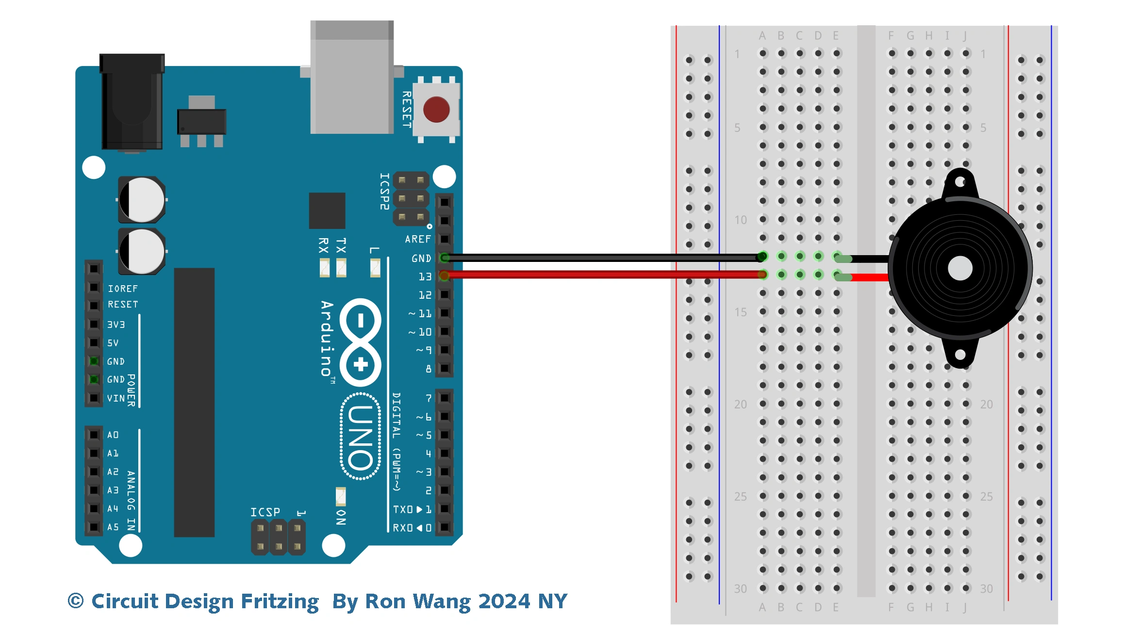
Project 2 S.O.S Morse Signal

// LED connected to pin 10
// Project 2 - LED SOS Morse Singal
/* Coding Ron Wang
   May 28th 2024
   Autaba support for coding hardware
 */
int ledPin = 10;
// run once, when the sketch starts
void setup()
{
 // sets the pin as output
 pinMode(ledPin, OUTPUT);
}
// run over and over again
void loop()
{
 // 3 dits
 for (int x=0; x<3; x++) {
 digitalWrite(ledPin, HIGH); // sets the LED on
 delay(150); // waits for 150ms
 digitalWrite(ledPin, LOW); // sets the LED off
 delay(100); // waits for 100ms
 }
 // 100ms delay to cause slight gap betyouen letters
 delay(100);
 // 3 dahs
 for (int x=0; x<3; x++) {
 digitalWrite(ledPin, HIGH); // sets the LED on
 delay(400); // waits for 400ms
 digitalWrite(ledPin, LOW); // sets the LED off
 delay(100); // waits for 100ms
 }
 // 100ms delay to cause slight gap betyouen letters
 delay(100);
 // 3 dits again
 for (int x=0; x<3; x++) {
 digitalWrite(ledPin, HIGH); // sets the LED on
 delay(150); // waits for 150ms
 digitalWrite(ledPin, LOW); // sets the LED off
 delay(100); // waits for 100ms
 }
 // wait 5 seconds before repeating the SOS signal
 delay(5000);
}