SAE J2601 Appendix A Fueling Protocol Rationale & Dev. Process 12
APPENDIX A - FUELING PROTOCOL RATIONALE AND DEVELOPMENT PROCESS
For the table-based fueling protocol described in Section 8, the SAE J2601 team used thermodynamic modeling and simulation to develop the tables listed in Appendices D and E. The simulations used the boundary conditions and process requirements listed in Sections 5, 6, and 8 to determine the appropriate average pressure ramp rate (APRR) and target pressure (end pressure) which met the goals discussed in 5.1. This appendix describes the modeling approach for the table-based fueling protocol. This protocol was developed for the fueling of Type III/IV CHSSs on road today. If other storage systems on vehicles are utilized, it is recommended that they be evaluated before implementing this protocol.
A.1 SIMULATION MODEL
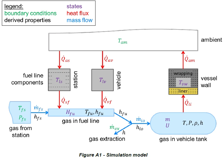
A numerical simulation model was employed to evaluate the evolution of gas pressure and temperature inside the CHSS. The components of this model are depicted in Figure A1. The fuel gas is delivered by the station with a given pressure 𝑃 𝑓𝑓𝑓 (corresponding to Pstation in Section 3) and a given fuel temperature 𝑇𝑇𝑓𝑓𝑓 (corresponding to Tfuel in Section 3). Both fuel pressure and temperature vary as the simulation proceeds, the pressure is ramped up with a linear dependence with respect to time, while the temperature may ramp down from ambient to a value in the respective fuel delivery temperature categories (see Section 8). The pressure drop between fuel station and vehicle CHSS is used in combination with a pressure drop coefficient to calculate the mass flow rate 𝑚𝑚̇𝑓𝑓𝑠𝑠 delivered by the dispenser. The specific enthalpy ℎ𝑓𝑓𝑓 is computed from its stationary contribution ℎ(𝑃 𝑓𝑓𝑓𝑓,𝑇𝑇𝑓𝑓𝑓𝑓) plus its dynamic contribution 𝑤𝑤𝑓𝑓𝑓𝑓2/2 with the gas velocity 𝑤𝑤𝑓𝑓𝑓𝑓. The fresh fuel from the station enters a control volume “gas in fuel line” where it exchanges heat with the thermal masses constituted by the fueling hose, pipes, and components. The thermal masses belonging to the station and to the vehicle are separate. Each thermal mass is characterized by its mass, specific heat capacity, and thermal conductivity. For each thermal mass, a set of ordinary differential equations is solved for their temperature. The thermal mass representing the station’s components was discretized in radial direction in order to allow for a one-dimensional temperature profile 𝑇𝑇𝑙 . The vehicle side was modeled with a lumped mass that has a homogeneous temperature 𝑇𝑇𝑓𝑓𝑓 . Both thermal masses exchange heat with the environment at ambient temperature 𝑇𝑇𝑎 , the respective heat fluxes are 𝑄𝑄̇𝑎 and 𝑄𝑄̇𝑎 𝑣 . They also exchange heat with the fuel gas in the control volume. A heat transfer coefficient based on a Nusselt equation for forced convection inside a pipe is used to compute the two heat fluxes 𝑄𝑄̇𝑠𝑠𝑠 and 𝑄𝑄̇𝑣 . They affect the enthalpy 𝐻 𝑓𝑓𝑓𝑓 of the gas in the fuel line, this is reflected in the fuel temperature 𝑇𝑇𝑓𝑓𝑓𝑓. The fuel gas then enters the CHSS with a specific enthalpy ℎ𝑓𝑓𝑓𝑓. The mass flow rate 𝑚𝑚̇𝑖 through the inlet/outlet port of each vehicle vessel equals the flow rate 𝑚𝑚̇𝑓𝑓𝑓 from the station divided by the number of identical vessels in the CHSS. In the case of multi-vessel systems, only one vessel is simulated as a representative. For this vessel, mass and energy balance are solved in order to obtain the gas mass 𝑚𝑚 and internal energy 𝑈𝑈 at any time. It is assumed that the gas inside the CHSS is perfectly mixed at all times, i.e., there are no spatial gradients. In the case of fueling the CHSS, the flow rate 𝑚𝑚̇𝑖 is positive and the inflowing gas carries the specific enthalpy ℎ𝑖 =ℎ𝑓𝑓𝑓𝑓. For a defueling/extraction simulation, 𝑚𝑚̇𝑖 is negative and the outflowing gas has the specific enthalpy of the gas inside the vessel, ℎ𝑖 =ℎ. All properties of the gas inside the vessel (e.g., 𝑃 ,𝑇𝑇,ℎ) are computed from the gas equation of state with the given density computed from the gas mass divided by the vessel volume, 𝜌𝜌=𝑚𝑚𝑉𝑉⁄ and the given specific internal energy from the total internal energy divided by the gas mass, 𝑢 =𝑈𝑈𝑚𝑚⁄. A highly accurate equation of state was used that describes all relevant real gas behavior (e.g., compressibility, Joule-Thomson effect). (See footnote under 3.12.) The heat transfer rate 𝑄𝑄̇𝑙 between gas and vessel internal surface (liner) is computed from a set of Nusselt equations for various geometries and for forced and free convection. The vessel wall is discretized in radial direction and the transient heat conduction equation is solved in one dimension. This yields the temperature profile 𝑇𝑇𝑣 𝑣𝑣inside the vessel wall at any given time. On the outer surface, the vessel wall exchanges heat with the environment, the heat transfer coefficient is again based on a set of Nusselt equations for various geometries and for free convection.
The hydrogen gas temperature in the CHSS increases during fueling due to the heat transferred from the station, vehicle thermal masses, the Joule-Thomson heating of the fuel as it is throttled through the fuel line orifices, and the heat of compression inside the CHSS. Different materials and designs of CHSSs will lead to different degrees of compressive heating during fueling due to differences in heat transfer characteristics, the heat capacity, and storage volume. The fueling protocol in this Standard is based on input from automotive OEMs and CHSS manufacturers on extreme-case heating in a CHSS that reflects the range of configurations of current storage technology. These extreme cases are described in the following sections. They influence fixed model parameters (e.g., masses, surface areas, volumes), initial conditions of all states for which ordinary differential equations are solved (e.g., 𝑇𝑇𝑙 , 𝑇𝑇𝑣 𝑣𝑣, 𝑚𝑚, 𝑈𝑈), and boundary conditions (e.g., 𝑇𝑇𝑎 ,𝑇𝑇𝑓𝑓𝑓 , 𝑚𝑚̇𝑒 𝑥𝑥).