SAE J2601 Appendix I MC Formula-Based Flow Charts 19
APPENDIX I - SAE J2601 MC Formula-Based Flow Charts
I.1 Introduction
As per 9.7, this appendix details the flow charts for MC Formula-based fueling. These flow charts provide an explanation of the control logic for MC Formula-based fueling. These flow charts are to be used in conjunction with the subroutines detailed in Appendix J. Where appropriate, a reference to the applicable section and/or equation of Appendix J is called out in the flow charts.
An overview to the subroutines flow charts is as follows:
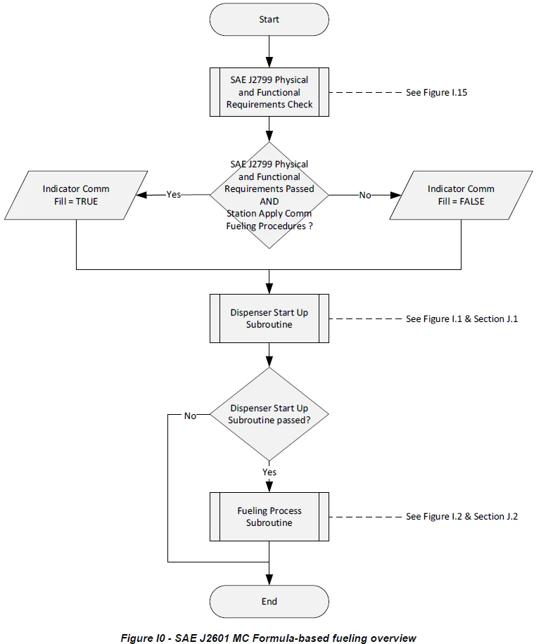
Figure I0 SAE J2601 MC Formula-based fueling overview
Figure I1 SAE J2601 MC Formula-based dispenser start up subroutine
Figure I2 SAE J2601 MC Formula-based fueling process subroutine
Figure I3 SAE J2601 MC Formula-based PRR control initialization subroutine
Figure I4 SAE J2601 MC Formula-based end pressure control initialization subroutine - ending pressure tables
Figure I5 SAE J2601 MC Formula-based end pressure control initialization subroutine - MC Method
Figure I6 SAE J2601 MC Formula-based mass average calculation subroutine
Figure I7 SAE J2601 MC Formula-based calculation of tfinal subroutine
Figure I8 SAE J2601 MC Formula-based calculation of Tcold subroutine
Figure I9 SAE J2601 MC Formula-based calculation of PRR and Pcontrol subroutine
Figure I10 SAE J2601 MC Formula-based determination of pressure targets and limits subroutine - ending pressure tables - page 1 of 2
Figure I11 SAE J2601 MC Formula-based determination of pressure targets and limits subroutine - ending pressure tables - page 2 of 2
Figure I12 SAE J2601 MC Formula-based determination of pressure targets and limits subroutine - MC Method
Figure I13 SAE J2601 MC Formula-based evaluate end of fill criteria subroutine
Figure I14 SAE J2601 MC Formula-based process check subroutine
Figure I15 SAE J2799 physical and functional requirements subroutine