Journey to Tibet | Day 09 Zhongba-Paya-Huoer-Tachin (Kangringboqe)
Day09:西藏之旅 - 仲巴-帕羊-霍尔-塔钦(冈仁波齐)
9月9日清晨迎着晨光我们从仲巴县城出发向冈仁波齐峰进发,从仲巴至帕羊镇的途中,新藏公路桑木张河段两岸会经过一片五彩沙漠,由于这里的山体岩石为红色,在高原阳光的照耀下,冷暖色浑为一体,形成了美丽的新月形五彩沙丘,非常神奇和壮观。
第一站帕羊 五彩沙漠

五彩沙漠

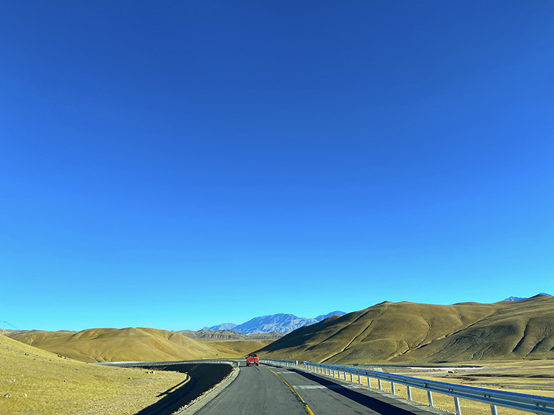
新藏公路

公路与山

雪山-湖泊 "措"
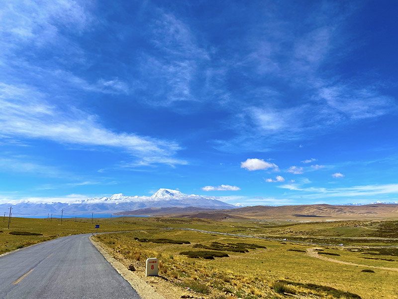
沿着新藏线笔直的公路,一路驰骋,沿途都是大片的高原湿地,湿地中清澈的水面将远处连绵的雪山映在水中,非常的壮美。高原牧场中马群的牛羊也让人迹罕至的世界屋脊显得生机勃勃。
藏西秘境 天上阿里
经过71公里的车程后我们便到达帕羊,公路两傍都是辽阔的草场和远处的雪山,在一马平川的公路行驶不久,将看到一座雄伟的大门,上面写着“藏西秘镜、天上阿里”过了这扇大门,我们就正式进入世界第三级阿里地区了。

藏西秘境——阿里

藏西秘境天上阿里

阿里边境检查站(停车后所有人到检查站检查登记)
过了阿里的大门,不久就翻越日喀则地区和阿里地区的界山,马攸木拉垭口(海拔:5216米),越过垭口,远远就见到一个蓝色的湖,就像一块蓝宝石埋藏在荒原之中,这就是公珠错湖。公珠错湖继续前行,不远处的圣湖-玛旁雍措烟波浩淼,神山山冈仁波齐峰头部的侧面展现眼前。

马攸木拉垭口

翻过垭口继续前行的公路
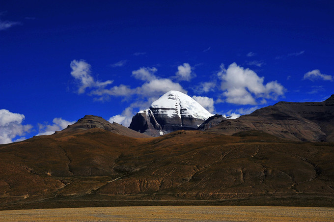
初见圣湖神山
这里路边会有很大的玛旁雍错景区的售票处和管理处,但是不知是因为疫情还是别的原因这里是不开放的,公路边上有写着玛旁雍错景区的石碑上面系满了经幡,玛旁雍错湖畔距离公里还有比较远的距离只能看看,拍照都不好看。这里可以远远的看见神山——冈仁波齐峰,远远的就可以看出它的与众不同,在这里很多游客驻足拍照,当地藏民在这个路口摆摊销售一些特色的小商品,我们也在此驻足拍照。

公路上初见圣湖的路标(从这里过去并不开放)

玛旁雍错初见

远处的圣湖——玛旁雍错

玛旁雍错景区边的商贩

这里远望神山
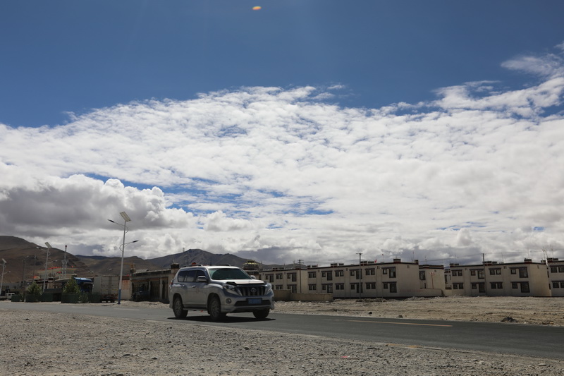
在这里停留拍照后继续前行会到达普兰县的霍尔镇,从霍尔镇到冈仁波齐峰还有大约43公里的距离。我们不是很清楚塔钦那边的状况,所以就决定在霍尔镇吃饭休息。霍尔是个乡镇,这里因为圣湖神山而存在较多的商业——饭店和住宿旅店,从这里我们感觉到物价比较贵,电网还没有通到这里,所以能源、资源都比较匮乏,但是也是有超市、水果蔬菜的,香蕉7-8元每斤,西红柿黄瓜5-6元每斤,我们去找了个川菜馆,宫保鸡丁40元,西红柿鸡蛋面25元(只能说能吃,味道比较差,做饭的人来自成都,每年在这里做4-6个月生意,回成都休息半年)。

霍尔停车吃饭 四川饭店

霍尔乡街道 一眼望到头

普兰——冈仁波齐路标
午饭后稍作休息驱车继续前行,向左边便可以到达普兰县(81KM),直行便可达到塔钦冈仁波齐。我们继续驱车前往神山——冈仁波齐峰。从霍尔出来后,往冈仁波齐大约四十多公里便可抵达冈仁波齐,这里有中石油加油站,有公路限速标牌。在驶出霍尔乡不久便可以看到远处的神山,我们也很激动,在路边停车与神山合影。

公路远处的神山——冈仁波齐峰
开车40分钟左右便可看到冈仁波齐的路标指示牌,向右行进,进去后先是检查站,检查所有人的身份证和边防证后便可以放行进入塔钦(冈仁波齐)。塔钦地方不大,但因为冈仁波齐峰神山而闻名国内外,今年因为疫情所以这里没有外国人的身影,否则这个季节外国游客前来转山的人数非常大。塔钦位置在山脚下,街区沿着山坡,我们到达时这里还在修路,修建一些宾馆和住宿地方,在下面的位置先是一些住宿的酒店,酒店往山下一点海拔低,另外也方便揽客。这里的几个主要的酒店:喜马拉雅冈仁波齐酒店旺季价格700~800元/间房,估计是当地价格最高的一家酒店,因为宣传做的好,所以网上订房及酒店入住率非常高。还有远方的家、冈底斯宾馆基本是400-600元/间,我们住在冈底斯宾馆后面的三峡宾馆(酒店老板电话陈彬 18989976899),老板和差不多大是从重庆每年过来几个月再次经营酒店,这家酒店价格比较实惠,房间也很干净,老板比较直爽,和我们聊怎么转山,有哪些注意的,后来我们还从他这里借了2根登山杖(注意:转山时每人最好携带两个登山杖会比较轻松和保护膝盖)。

抵达冈仁波齐的路牌

美丽的太阳光晕(源头彩虹)

冈底斯宾馆-远方的家-喜马拉雅冈仁波齐酒店

冈底斯宾馆(建设中)
 塔钦喜马拉雅冈仁波齐酒店700-800元/间


东北饺子馆,只有一种馅(大肉白菜),20元/份
这次我们找了一家东北饺子,价格还挺便宜的但是就只有一种馅,口味吃起来算是非常不错的了,所以我们在塔钦基本都是吃饺子了(其实,就吃了一顿饭,第二天凌晨6点就披星戴月的转山了,回来已是9月11日晚上9点多)。下面可以看到建设中的塔钦,越野车开过石头堆积的卵石路,才能到达上面的商铺走到冈仁波齐峰转山的起点入口处,当地生活的主要是藏民,看出紫外线超强,人都皮肤黝黑,被称为东方吉普赛人。当地的妇女妈妈以一种特有的背囊背着幼童,在转山路上我们也遇到她们这样背着小孩转山。

塔钦风景-建设中的塔钦

塔钦街景
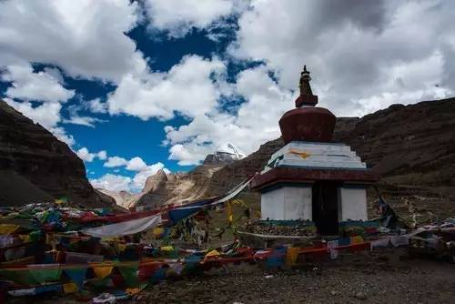
今夜我们就在这里休息,下午在塔钦街上逛了逛,准备在经幡广场或者卓玛拉山口挂经幡,在当地的经幡铺看看经幡的价格,由于我们人多,所以购买了15付经幡,所以做经幡生意的藏民大哥就答应带我们第二天早上6点去经幡广场,把经幡挂在最高处。因为在经幡广场经幡可以挂一年,在卓玛拉山的经幡只能挂一个月就会被人撤换掉了。所以我们就决定把所有经幡挂在经幡广场。

经幡舞动,诵经不断
塔钦经幡广场远处的冈仁波齐峰