Journey to Tibet | Day 13 Pulan - Lha'ang Co - Menshi - Zada Earth Forest
Day13:西藏之旅 - 普兰-拉昂错-门士-札达土林-札达
今天在普兰睡个懒觉,大家在这里待到11点多,把厚衣服及睡袋等都整理起来,因为后面的行程不会在户外有比较冷的地方。在普兰的超市补充了瓶装水、面包、零食之后,我们边驾车出发了。离开普兰胜境大牌楼时是中午12点多。后来,我们依然在拉昂错、玛旁雍错两个湖边停留拍照,100公里的路程,我们开到塔钦附件的中石化加油站时已经是近下午两点多钟。

普兰县全景
G565的盘山公路
从塔钦到门士63公里,从门士到札达168公里,在G219国道上走51公里后,左转进入G565国道向札达县城出发,这个路线我们没有研究,当我开上之后,才知道这条路有多疯狂,进入G565后一共是117公里的路程到札达县城,路上一共翻越两座海拔5000米以上的垭口,其中的盘山路比去珠峰时的蜿蜒曲折也不少。

蜿蜒盘旋的公路

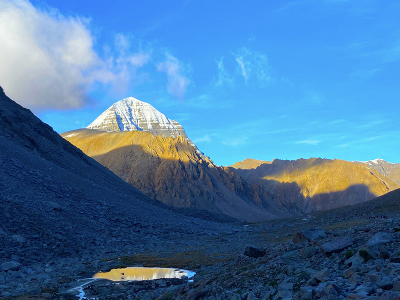
进入G565一会就开始开始翻越隆嘎拉山(海拔5160m)我们用手机GPS实测两座山垭口一个5300米,一个是5400米垭口,走完这些蜿蜒的盘山路后,后面的山体颜色变得五彩斑斓,一路尽是没完没了的山,上上下下,转来转去的,感叹这路是这次西藏之行可把盘山道给开够了。

下午6点45分的阳光依然这么耀眼,透着美丽的源头彩虹光晕

恶劣天气和低能见度公路指示标

绵延的群山

手机GPS实时测得翻越公路的海拔高度

高原山脉,层层叠叠
札达人民欢迎您
札达县(Zanda County),藏文རྩ་མདའ་རྫོང་། ,意为“下游有草的地方”,隶属中华人民共和国西藏自治区阿里地区,阿里地区下辖县。 位于西藏自治区西部、象泉河流域, 为阿里地区边境县之一。总面积24601.59平方千米。总人口1万人(2003年),是全国人口最少的县。县人民政府驻托林镇托林居委会。札达县除少数汉族、回族外均为藏族。县政府驻地托林镇,海拔3700米,距拉萨1760公里。为该县政治、经济、文化的中心。
札达,原为扎布让宗和达巴宗属地。1956年10月两宗合并,设立札达宗办事处。1960年5月建立札达县,属阿里地区管辖。札达境内著名的古格王朝遗址是全国重点文物保护单位。全县耕地面积11万亩,森林面积37万亩,草场面积3190万亩。辖6个区,15个乡,60个村民委员会。
2018年9月25日,获得商务部“2018年电子商务进农村综合示范县”荣誉称号。 2019年2月6日,西藏自治区人民政府决定札达县退出贫困县。

札达人民欢迎您,前面200米处就是札达边境检查站

群山盘绕的公路
札达土林
札达最著名的地貌风光区,就是札达土林。札达土林地貌发育最好的地区是以托林镇为中心的大片地区,分布高度是海拔3750-4450米,面积约888平方公里,札达土林分布的总面积约为2464平方公里,是世界上最典型、分布面积最大的第三系地层风化形成的土林。扎达土林地貌在地质学上叫河湖相,成因于百万年的地质变迁。地质学家考证,一百多万年前,扎达到普兰之间是个方圆500多公里的大湖,喜马拉雅造山运动使湖盆升高,水位线递减,逐渐冲磨出“建筑物”惟妙惟肖的形状与层高,数十万年风雨的侵蚀,犹如神工鬼斧不间断地雕琢打磨,更使他玲珑剔透、出神入化。放眼望去,满眼的金碧辉煌,在高原迷幻光影的衬托下,宛若神话世界。驻足四望,雪山下的土林绵延起伏,土林如海,印证了“土林包围的地方”这一称号。连绵起伏的雪山在阳光下散发着耀眼的光芒,与黄褐色的土林构成完美而壮观的画卷。公路在进入宽阔的象泉河谷后,我们便会到达今晚的休息住宿地札达县。

札达土林国家地质公园

夕阳染红的土林

连绵土林


土林

蓝天映衬下的土林-骆驼峰

看山望月

独占鳌头

层山尽染

高山草原的公路

连绵不绝

层岚叠嶂,错落有致

扎达土林

土林夕阳

扎达土林银河(网友摄)

托林寺大门
抵达札达县城时记得应该是晚上9点钟,天刚刚黑,札达虽然旅游业没有完全开展,但是我们到这里没有订房间,然后打了差不多十多家酒店都是满房的,可见这里的旅游人数之多,最后我们住在热布加林村宾馆,标间280元,三人间是350元。