eerer
eerer…
撰写内容中………
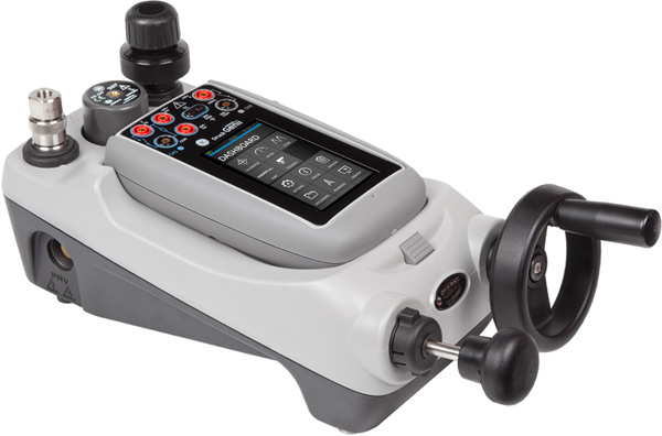
Diagnostic and calibration pressure hoses are essential tools in various industries for ensuring the…
Install MariaDB 10.8 on CentOS 8 These are the ideal steps you’ll go through when installing MariaDB…
Name (*)