SAE J2601:2020 Scope 01
SAE 2601 Scope
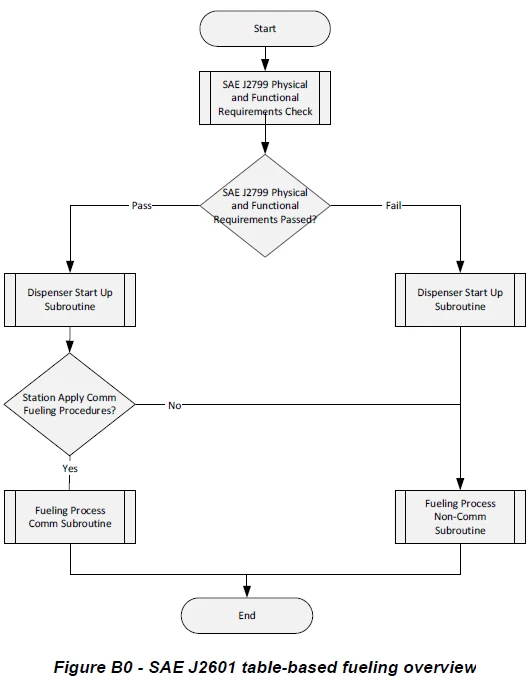
SAE J2601 establishes the protocol and process limits for hydrogen fueling of vehicles with total volume capacities greater than or equal to 49.7 L. These process limits (including the fuel delivery temperature, the maximum fuel flow rate, the rate of pressure increase, and the ending pressure) are affected by factors such as ambient temperature, fuel delivery temperature, and initial pressure in the vehicle’s compressed hydrogen storage system. SAE J2601 establishes standard fueling protocols based on either a look-up table approach utilizing a fixed pressure ramp rate, or a formula-based approach utilizing a dynamic pressure ramp rate continuously calculated throughout the fill. Both protocols allow for fueling with communications or without communications. The table-based protocol provides a fixed end-of-fill pressure target, whereas the formula-based protocol calculates the end-of-fill pressure target continuously. For fueling with communications, this standard is to be used in conjunction with SAE J2799.
An important factor in the performance of hydrogen fueling is the station’s dispensing equipment cooling capability and the resultant fuel delivery temperature. There are three fuel delivery temperature categories denoted by a “T” rating: T40, T30, and T20, where T40 is the coldest. Under reference conditions, SAE J2601 has a performance target of a fueling time of 3 minutes and a state of charge (SOC) of 95 to 100% (with communications), which can be achieved with a T40-rated dispenser. However, with higher fuel delivery temperature dispenser ratings (T30 or T20) and/or at high ambient temperatures, fueling times may be longer.
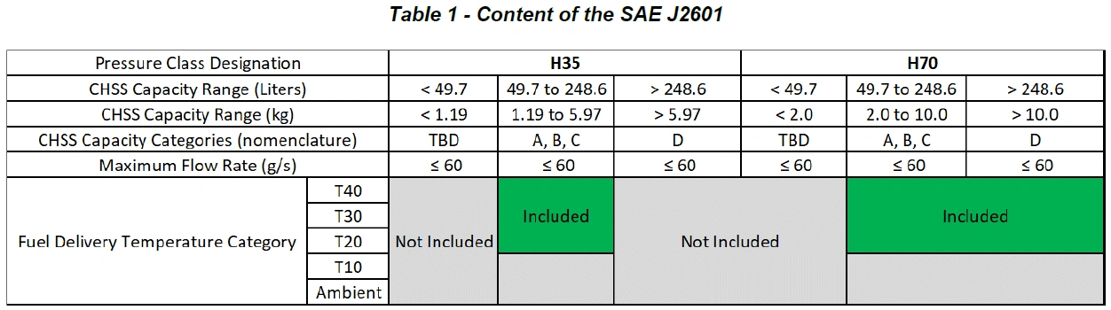
Table 1 depicts the scope of SAE J2601 and potential work items for future revisions within this or other documents of the SAE J2601 series. SAE J2601 includes protocols which are applicable for two pressure classes (35 MPa and 70 MPa), three fuel delivery temperatures categories (-40 °C, -30 °C, -20 °C) and compressed hydrogen storage system sizes (total volume classification) from 49.7 to 248.6 L (35 MPa H35, and 70 MPa H70), and from 248.6 L and above (H70 only). Future versions of SAE J2601 work may incorporate warmer fuel delivery temperatures (-10 °C and ambient) and smaller total volume capacities for motorcycles and other applications.
The fueling protocols herein were developed based on a set of key assumptions described in Section 7 and Appendix A. These assumptions should be carefully considered in the development and implementation of an on-board compressed hydrogen storage system. In particular, hydrogen storage systems with properties which do not fall within the parameters in Table A3 should be further evaluated to confirm compatibility with the protocols herein.