SAE J2601:2020 Definitions 03
SAE J2601 Part 3 Definitions
3.1 AVERAGE PRESSURE RAMP RATE (APRR)
The average increase in pressure (MPa/min) from the start of fueling to the end of fueling.
3.2 COMPRESSED HYDROGEN STORAGE SYSTEM (CHSS)
The Compressed Hydrogen Storage System CHSS (refer to SAE J2579) consists of the pressurized containment vessel(s), pressure relief devices (PRDs), shut off device(s), and all components, fittings and fuel lines between the containment vessel(s) and the shut off device(s) that isolate the stored hydrogen from the remainder of the fuel system and the environment.
3.3 CHSS CAPACITY
The total water volume of the CHSS in liters, or the total mass of hydrogen stored in the CHSS at the nominal working pressure (at 15 °C / 59 °F ), which is equivalent to the CHSS 100% state of charge.
3.4 CHSS CAPACITY CATEGORIES
The CHSS capacity category is a range of CHSS capacities which may fuel in a similar manner by a fueling protocol.
3.5 DISPENSER COMPONENTS
Any component of the dispenser that carries pre-cooled hydrogen to the CHSS. In most cases, this is any component downstream of the heat exchanger up to and including the nozzle; e.g., hose breakaway, dispenser hose, and nozzle.
3.5.1 HYDROGEN DISPENSING EQUIPMENT
The equipment required to condition and transfer fuel from the station to vehicle CHSS for the purpose of fueling the vehicle.
3.5.2 CONNECTOR OR COUPLING
A joined assembly of a nozzle and receptacle which permits rapid coupling (or connecting) and decoupling (or disconnecting) of fuel supply nozzle to the vehicle fueling receptacle, as per SAE J2600.
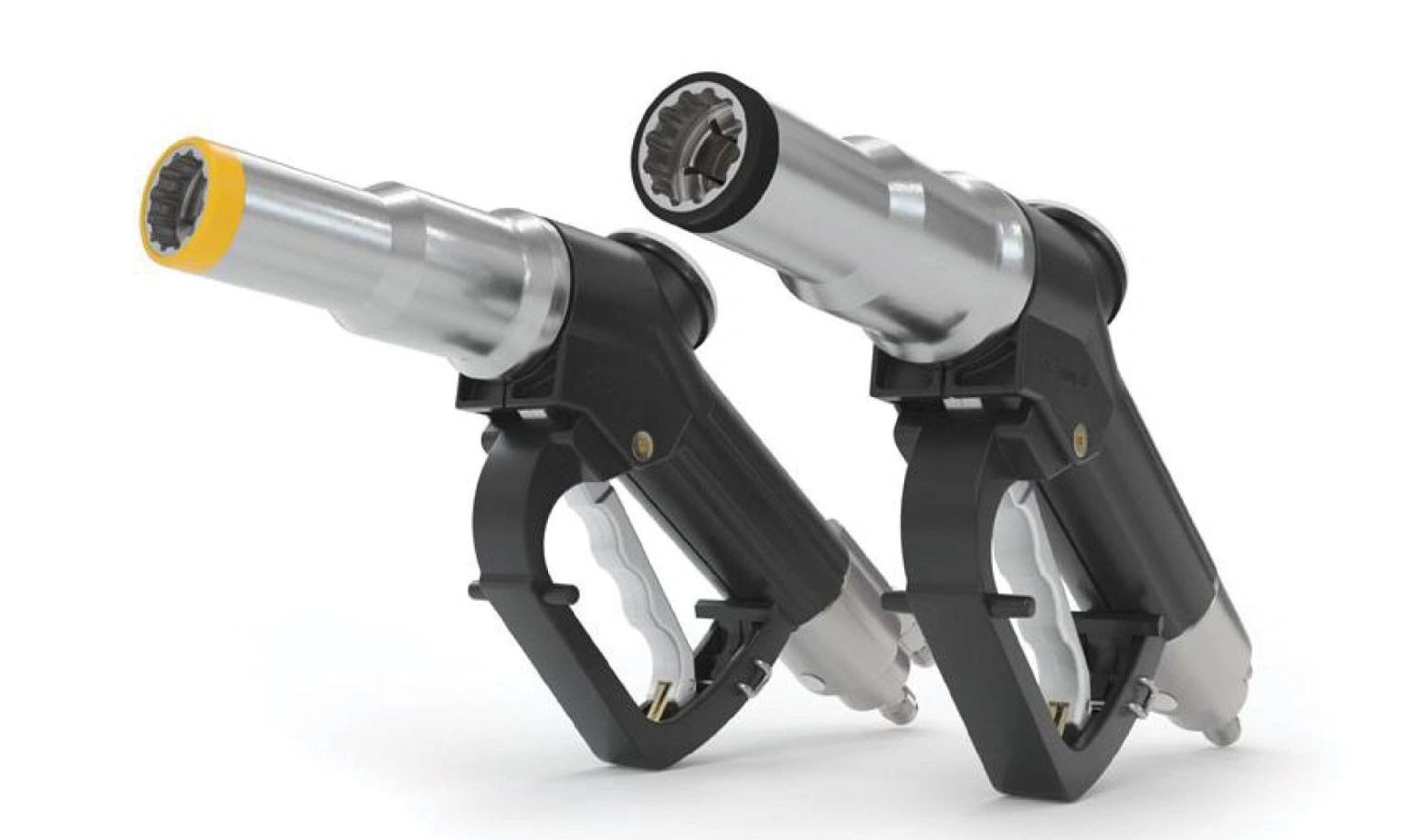
3.5.3 NOZZLE
Device connected to a fuel dispensing system which engages the hydrogen surface vehicle (HSV) receptacle and permits transfer of fuel (see CONNECTOR or COUPLING).
3.5.4 RECEPTACLE
Device connected to a vehicle or storage system that receives the dispenser nozzle and permits transfer of fuel. This may also be referred to as a fueling inlet (see CONNECTOR or COUPLING).
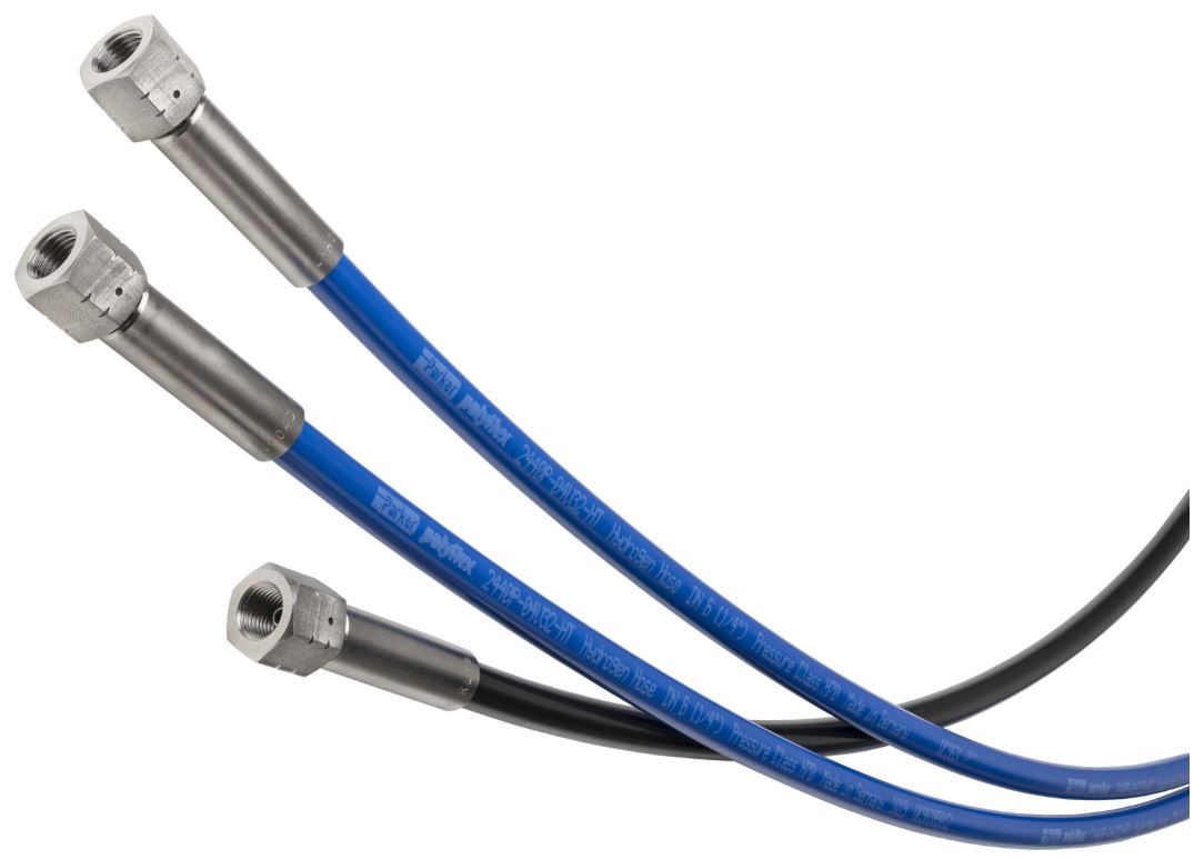
3.5.5 DISPENSER HOSE
The flexible hose assembly which transfers hydrogen between the dispenser and nozzle.
3.5.6 HOSE BREAK-AWAY
A device which allows the hose to separate from the dispenser if exposed to a sufficient mechanical stress. Typically, the hose is the only component between the nozzle and hose break-away.
3.6 Fueling with Communications and Non-communications
3.6.1 COMMUNICATIONS
Communications fueling means that a valid data connection has been established from vehicle to fueling station dispenser as described in SAE J2799.
3.6.1.1 NON-ASIL/SIL COMMUNICATIONS ASSUMPTION FOR SAE J2601
The IrDA communications defined in SAE J2799 2024 has not been ASIL/SIL classified to any standard at the time of publishing this standard. This means until ASIL/SIL certification is achieved, the signals are not guaranteed to be accurate and the station is responsible to ensure that process requirements are followed if it uses the communications signals.
The following are some of the guidelines that may be used to qualify components and systems for the station side SIL: IEC 61508/61511 and for vehicle side ASIL: ISO 26262.
3.6.2 NON-COMMUNICATIONS
Non-communications means that no valid data connection from vehicle to fueling station dispenser as per SAE J2799 exists, or that the received data has not been recognized as valid (or wished to be used) by the dispenser.
3.7 FUELING PROTOCOL CATEGORIES
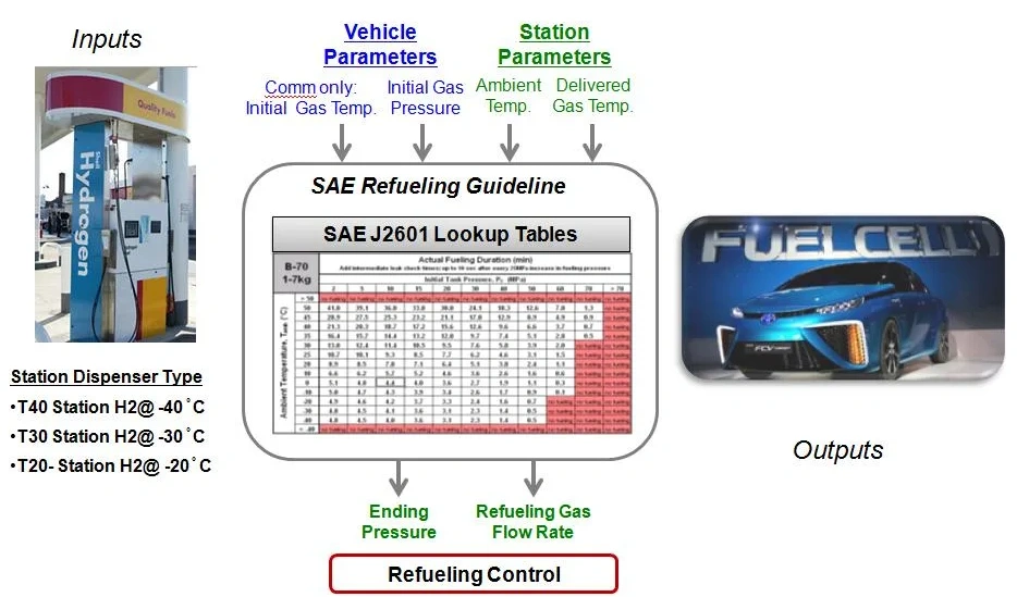
Station fueling protocol will be defined by the vehicle's nominal working pressure (NWP) and the station's fuel delivery temperature category. The category is denoted by the letter H followed by the nominal working pressure in MPa, a hyphen, and the letter T followed by the absolute value of the fuel delivery temperature category in degrees celcius. For example, H70-T40 is the station category for a hydrogen fueling protocol with a NWP of 70 MPa and a fuel delivery temperature category of -40 °C.
3.8 FUELING PROTOCOL STANDARDIZATION
3.8.1 STANDARD FUELING PROTOCOL
A fueling protocol which has been reviewed and approved by the SAE Fuel Cell Standards Interface Task Force and is defined in the main body of SAE J2601. In this current version of SAE J2601, the standard fueling protocols are the table-based (Section 8), and MC Formula-based (Section 9).
3.8.2 NON-STANDARD, DEVELOPMENT FUELING
A fueling protocol which has not yet been reviewed and approved by the SAE Fuel Cell Standards Interface Task Force and thus is not defined in the main body of SAE J2601.
3.9 FUELING TIME AND FUELING EVENTS
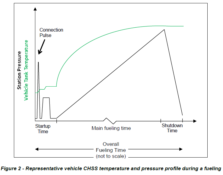
Figure 1 illustrates the fueling time definitions for the main and overall fueling time as described in 3.9.1 to 3.9.8.
3.10 HYDROGEN SURFACE VEHICLE (HSV)
Any surface vehicle which stores and uses hydrogen as a fuel. An example of an HSV is a fuel cell vehicle.
3.11 PRESSURE
3.12 STATE OF CHARGE (SOC)
The ratio of CHSS hydrogen density to the density at NWP rated at the standard temperature 15 °C. SOC is expressed as a percentage and is computed based on the gas density per Equation 1.
3.13 SOCvehicle
SOC calculated with CHSS pressure and CHSS temperature.
3.14 SOCstation
SOC calculated with station pressure and CHSS temperature.
3.15 STATION DESIGNATION
Stations are to be designated by their pressure class and fuel delivery temperature category. For example, a station with a NWP pressure class of 70 MPa and fuel delivery temperature category of T40 is designated to be H70-T40.
3.16 TEMPERATURE
3.16.1 AMBIENT TEMPERATURE (Tamb)
3.16.2 CHSS AVERAGE VEHICLE GAS TEMPERATURE (Tvehicle)
3.16.3 CHSS MEASURED TEMPERATURE (MT)
3.16.4 CHSS SOAK TEMPERATURE
3.16.5 FUEL DELIVERY TEMPERATURE (Tfuel)
3.16.5.1 INSTANTANEOUS FUEL DELIVERY TEMPERATURE (Tfuel-inst)
3.16.5.2 TOTAL MASS AVERAGE FUEL DELIVERY TEMPERATURE (Tfuel-ave)
3.16.5.3 ROLLING MASS AVERAGE FUEL DELIVERY TEMPERATURE (Tfuel-ave-roll)
3.16.5.4 MASS AVERAGE FUEL DELIVERY TEMPERATURE (MAT0)
3.16.5.5 EXPECTED MASS AVERAGE FUEL DELIVERY TEMPERATURE (MATexpected)
3.16.5.6 THIRTY SECOND MASS AVERAGE FUEL DELIVERY TEMPERATURE (MAT30)
3.16.5.7 CONTROL MASS AVERAGE FUEL DELIVERY TEMPERATURE (MATC)
3.16.6 FUEL DELIVERY TEMPERATURE CATEGORY
3.16.7 DISPENSER COMPONENT TEMPERATURE MEASUREMENT